


 en
 English
 русский
 Español
 عربى
 Français
 Português
10+
Years Experience

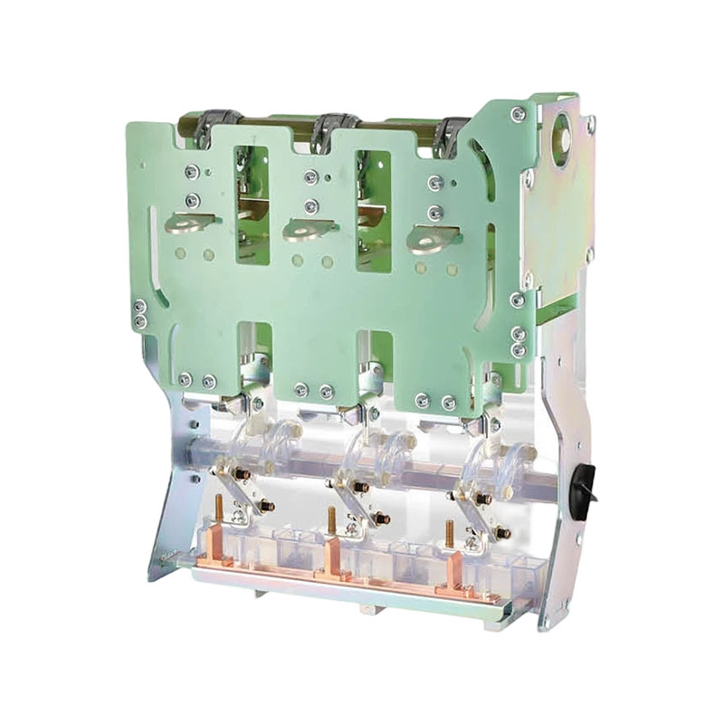
Our inflatable cabinet accessories series mainly supports the core components of eco-friendly gas-insulated switchgear (C-GIS) and solid-insulated ring main units, covering circuit breakers, environmental protection cabinet breakers, load switches, grounding switches, spring operating mechanisms, and solid insulation circuit breakers — an ideal upgrade solution to replace traditional inflatable cabinet breakers.
The products are compact, low-maintenance, long-lasting, cost-effective, and reliable, meeting AC high-voltage circuit breaker requirements such as GB1984 and GB/T1984, with a main circuit breaking capacity of up to 25kA and a mechanical life of over 10,000 operations. Customized component solutions and bulk supply are available based on the customer's cabinet dimensions and specific requirements.

Wenzhou Xubian Electric Co., Ltd. is a technology-driven China RMU & GIS Components Manufacturer and Custom RMU & GIS Components Supplier, specializing in the production, sales and after-sales maintenance of high- and low-voltage complete switchgear systems.
We have a dynamic and innovative team for R&D, design, management and marketing, backed by solid R&D and production competence.
Following our quality policy: “Survival through Quality, Development through Innovation, Continuous Improvement, Customer Satisfaction”, we enforce strict control over all production stages to ensure 100% qualified finished goods. Our workshop is well‑equipped with full‑range processing facilities, testing apparatus and advanced inspection solutions.
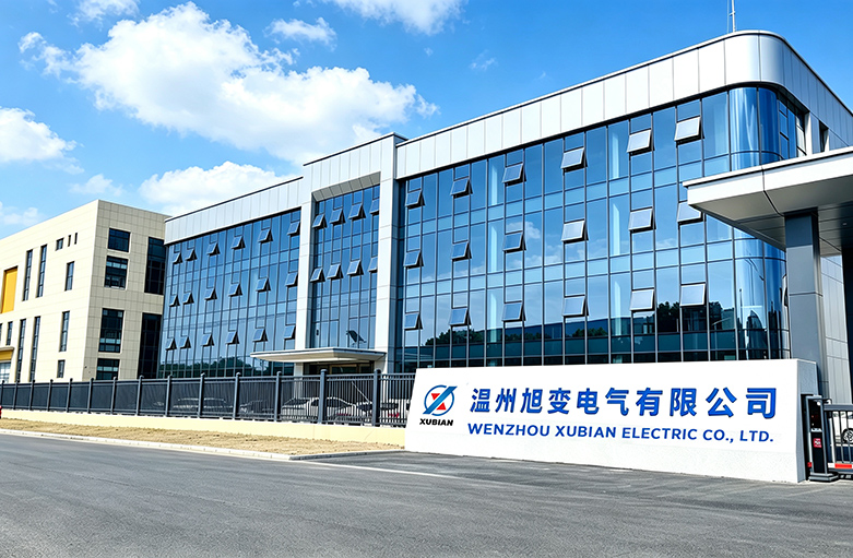
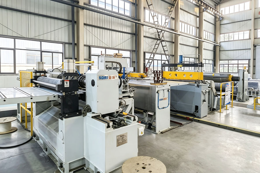
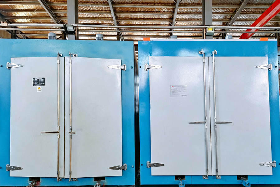
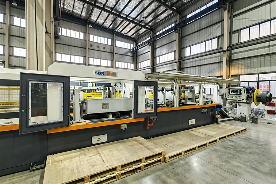
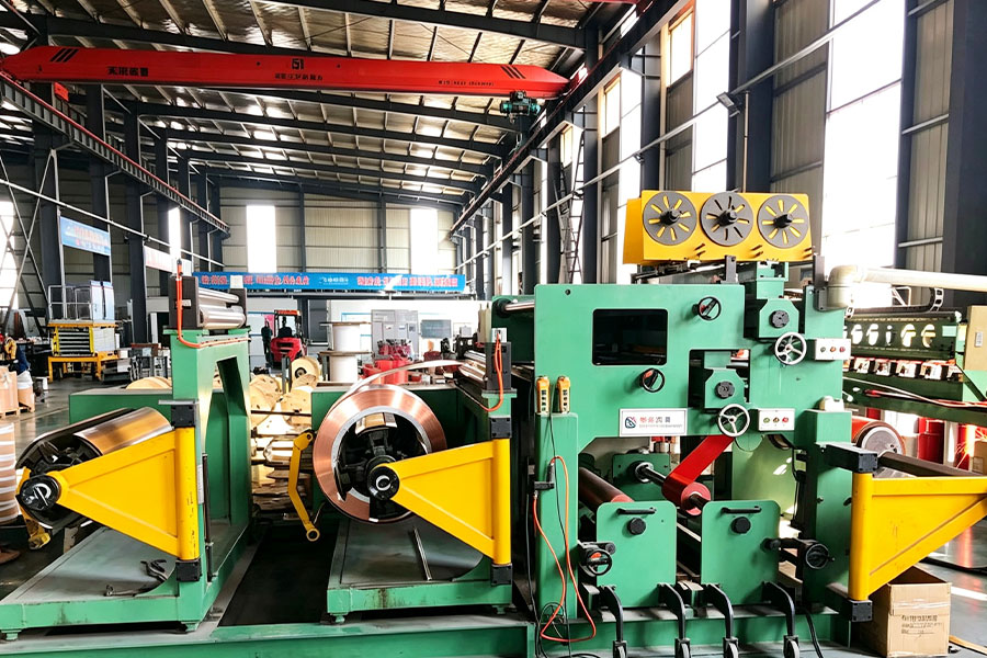
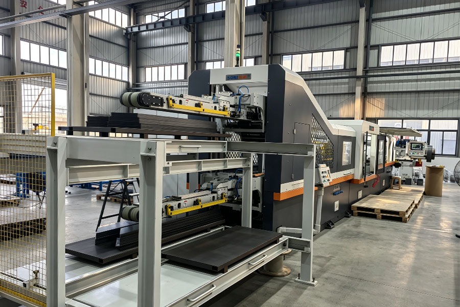
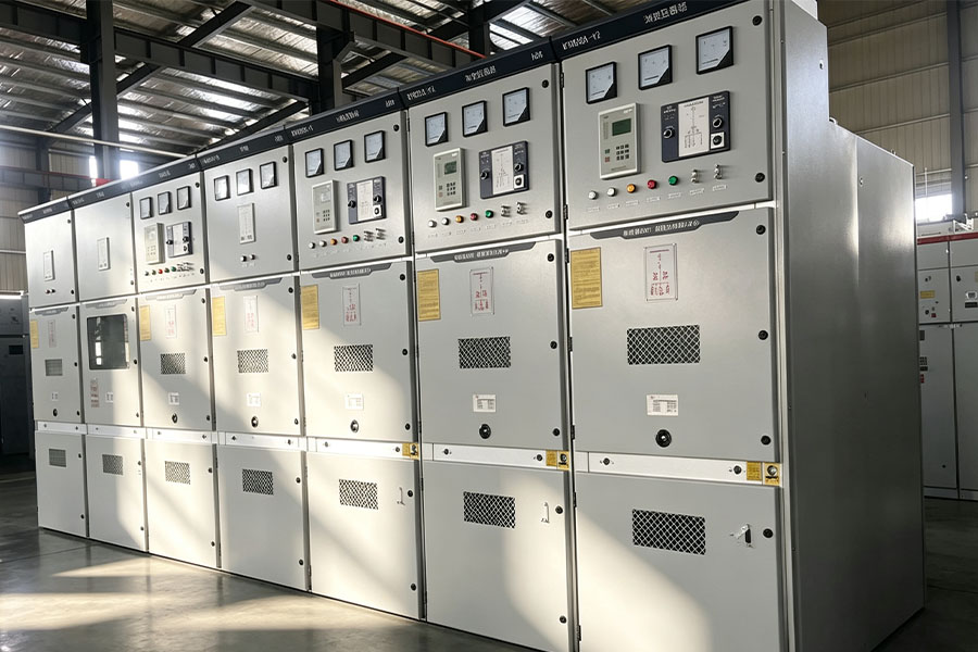
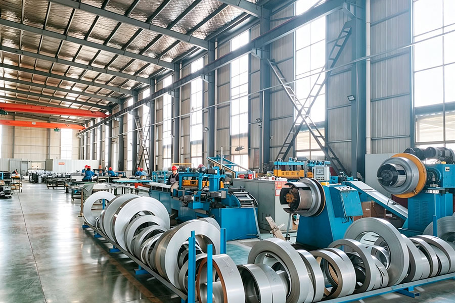
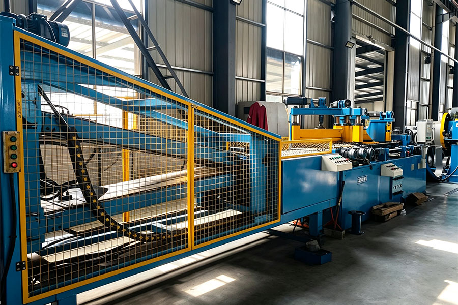
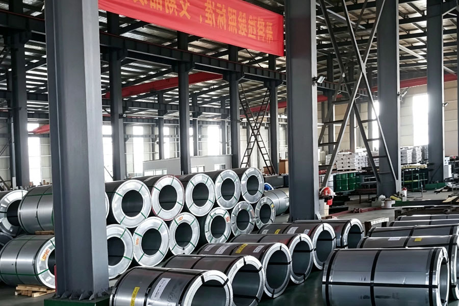
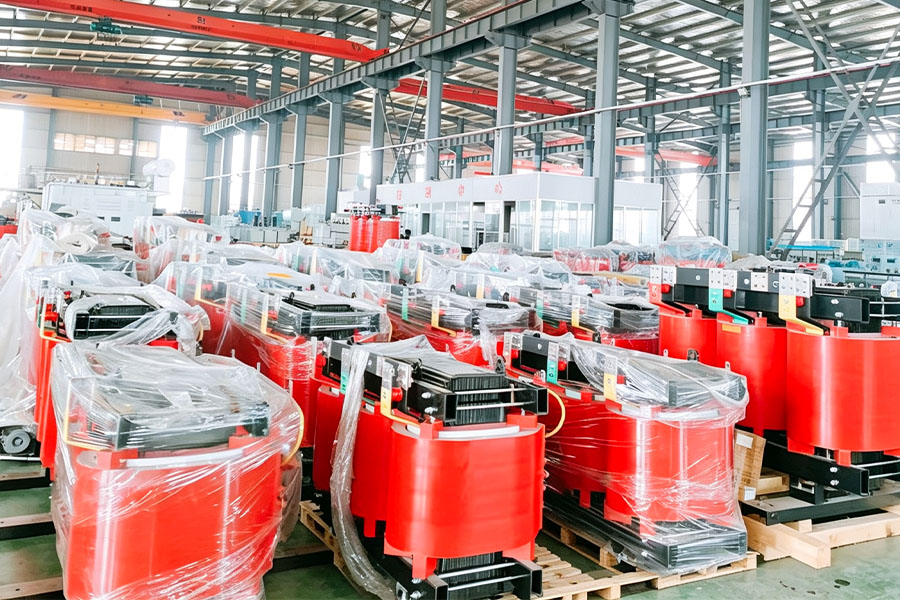
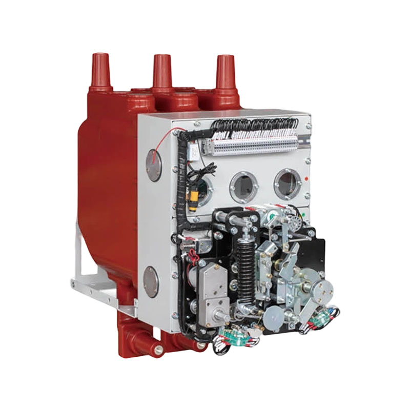
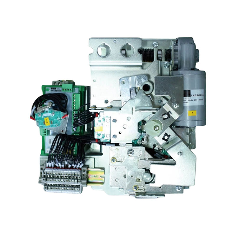
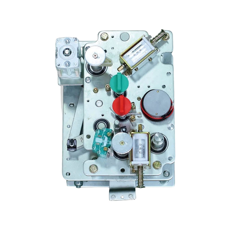
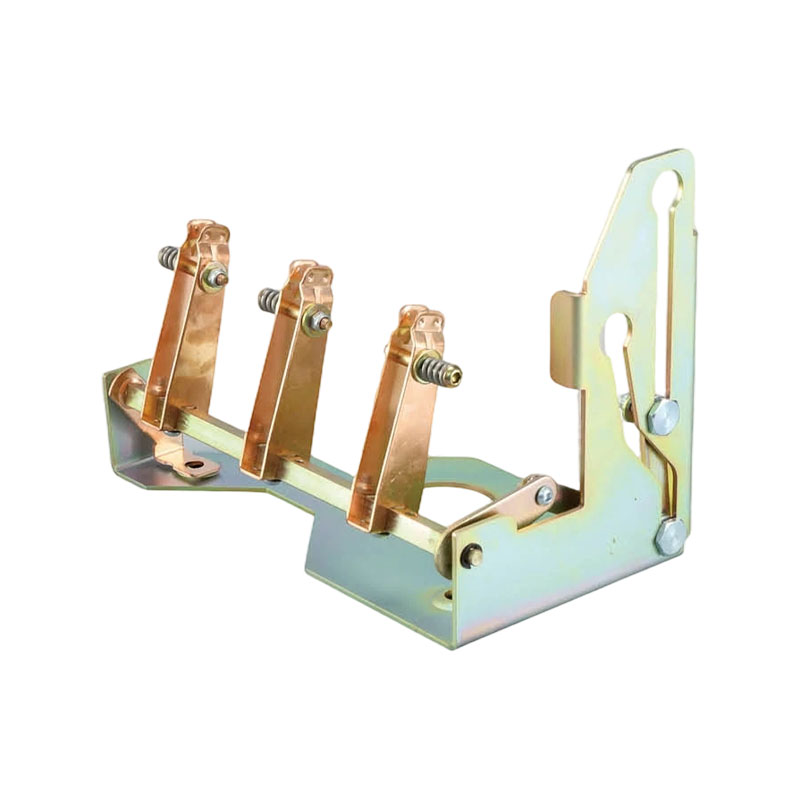
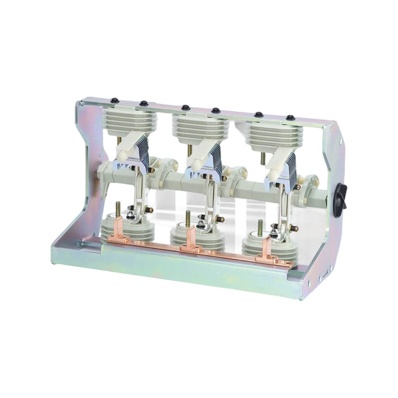
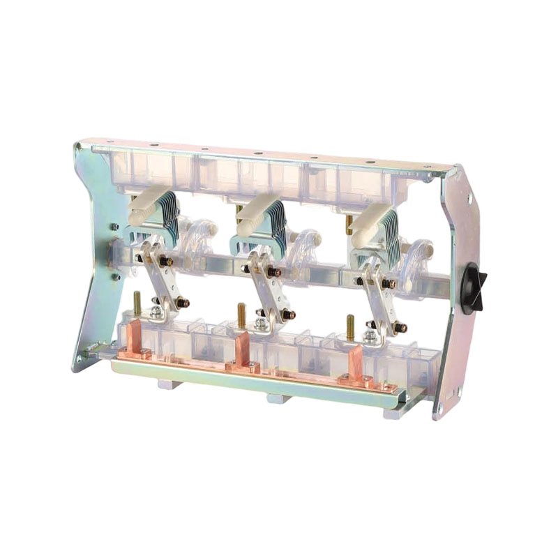
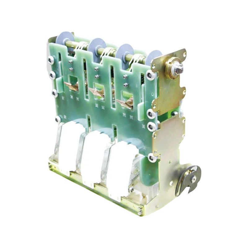
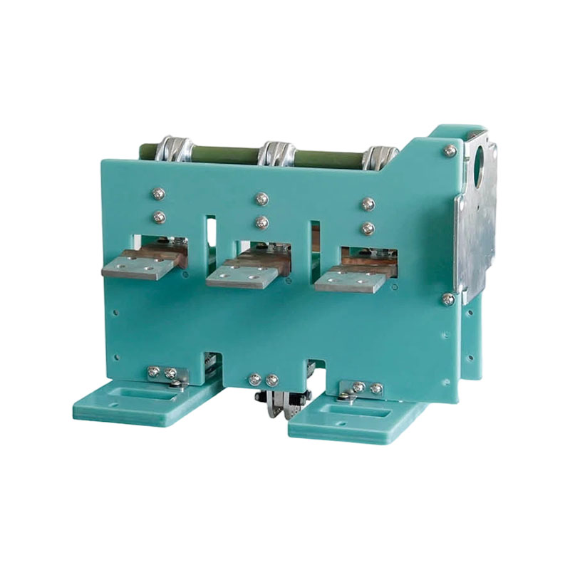
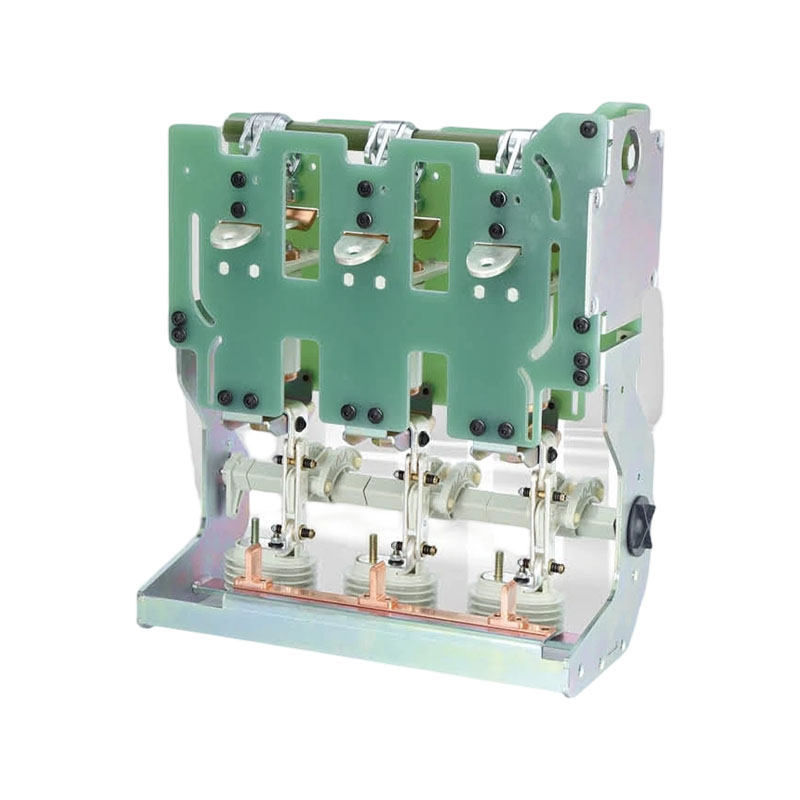
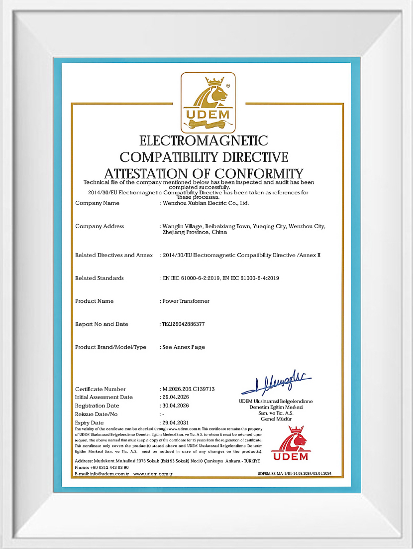
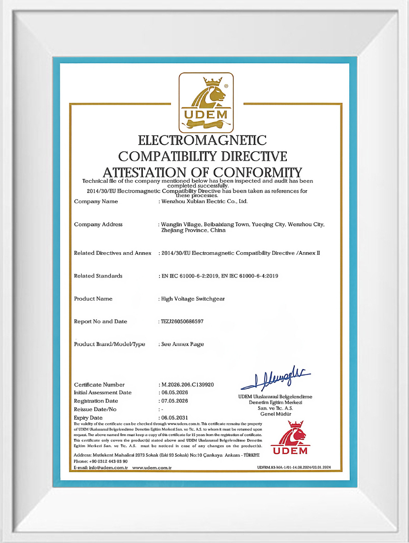
Wenzhou Xubian Electric Co., Ltd. manufactures the switching cores that sit inside sealed gas-insulated cabinets: 12 kV vacuum circuit breakers, load switches, earthing switches, spring operating mechanisms and solid-insulation breakers. As a China RMU & GIS components manufacturer, we supply these components on their own to cabinet builders and retrofit projects, and as part of the complete medium-voltage switchgear built in our Liushi workshop.
The Inflatable Cabinet Accessories Series manufacturer range covers the parts that decide the electrical and mechanical behaviour of a C-GIS or solid-insulated ring main unit — the devices that interrupt fault current, isolate a feeder and earth a compartment before work begins.
As a RMU & GIS Components Manufacturer, we match product configuration to the application, operating limits, interfaces and acceptance criteria defined for each project.
The range is organised by function inside the cabinet rather than by catalogue order. A single C-GIS panel normally takes one breaker or load switch, one earthing switch and one spring operating mechanism, so the components are quoted together against the panel scheme.
| Component | Model | Rating | Life | Position in the cabinet |
|---|---|---|---|---|
| Vacuum circuit breaker, grounded, with isolation belt | FKV-12kV-630A; FKV-12kV-630A New | 12 kV, 630 A, 20/25 kA | 10,000 operations main; earthing 20 kA, 5,000 operations | Incoming and outgoing feeders; the New version is the revised build of the same frame |
| Vacuum circuit breaker | FKV-12kV-1250A | 12 kV, 1250 A, 20/25 kA | 10,000 operations main; earthing 5,000 operations | Higher-current feeders, bus-tie and transformer circuits |
| Environmental protection cabinet circuit breaker | FKHB-630A | 12 kV class, 630 A frame | Per model data sheet | Dry-air and eco-friendly cabinets replacing high-GWP insulating gas |
| Load switch | FKC-12kV-630A; FKC-12kV-630 New | 12 kV, 630 A | Per model data sheet | Transformer feeders and ring positions needing load-current switching with visible isolation |
| Earthing switch | FKF-12 | 12 kV | Per model data sheet | Maintenance earthing of cable and busbar compartments |
| Spring operating mechanism | FK-12 V-type; FK-12 CF-type | 12 kV mechanism family | Matched to the breaker or switch it drives | Stored-energy operation of the breaker or load switch inside the cabinet |
| Solid-insulation circuit breaker | FKSIS-12/T(D)630A-25kA | 12 kV, 630 A, 25 kA | Per model data sheet | Solid-insulated RMUs and gas-free compact switchgear |
These accessories are built as replacement and new-build cores for sealed cabinets. In an inflatable cabinet — the common designation for a gas-insulated C-GIS panel — the breaker, load switch and earthing switch share one small tank, so component height, contact gap and the isolation belt arrangement have to match the tank geometry exactly.
The same components carry over to solid-insulated ring main units, where the FKSIS-12/T(D)630A-25kA breaker replaces the gas-insulated interrupter in a cast-resin or epoxy-encapsulated structure. Typical duty is 12 kV distribution: urban ring nodes, industrial plant substations, commercial buildings, and renewable-energy collection points where compact footprint and low maintenance matter.
The published parameters below are what we work from when checking a component against a cabinet drawing. They are the values printed on the data sheet and repeated in the factory test report for each unit.
| Parameter | Unit | FKV 12 kV breaker family |
|---|---|---|
| Rated voltage | kV | 12 |
| Rated frequency | Hz | 50 |
| Rated current | A | 630 / 1250 |
| Rated short-time withstand current | kA | 20 / 25 |
| Rated peak withstand current | kA | 50 |
| Rated short-circuit duration | s | 4 |
| Rated short-circuit making current | kA | 50 |
| Rated operating sequence | — | O-0.3s-CO-180s-CO |
| Main circuit resistance | µΩ | ≤ 40 |
| Contact gap | mm | 8.5 ± 1 |
| Overtravel | mm | 2–3 |
| Contact bounce | ms | ≤ 2 |
| Average opening / closing speed | m/s | 1.2 ± 0.2 / 0.6 ± 0.2 |
| Three-phase opening / closing non-simultaneity | ms | ≤ 2 |
| Mechanical life, main / earthing circuit | operations | 10,000 / 5,000 |
The 1250 A frame keeps the same 20/25 kA breaking class with a larger main circuit, so feeder cables, current transformers and busbar supports in the cabinet must be sized to the higher continuous current rather than to the breaker alone.
A sealed cabinet only stays reliable when the component is applied inside the environment it was designed for. The standard envelope for this series is stated on every data sheet:
Projects at higher altitude, in coastal salt-mist zones or in heavily polluted industrial air need the condition raised at enquiry stage, before the arrangement drawing is frozen, so the insulation and surface treatment can be reviewed together with the cabinet design.
The FK-12 V-type and CF-type spring operating mechanisms convert a manual or motor-driven charging action into a stored-energy close and open. The breaker's rated sequence, O-0.3s-CO-180s-CO, is achieved through the mechanism's spring energy rather than through the operator, which is why mechanism selection is confirmed together with the interrupter and not afterwards.
When you send a cabinet scheme, we compare three interfaces: the mounting footprint and fixing centres, the drive coupling between mechanism and breaker shaft, and the isolation belt and earthing arrangement on the grounded versions. Interlock logic belongs to the cabinet design, so the mechanical interfaces we provide are dimensioned to accept your existing interlock linkage.
The same engineering check applies where the component is going into one of our own assemblies, such as the 12kV medium voltage complete switchgear, where breakers, load switch series components and earthing switches are assembled and tested as one functional unit.
Components are inspected at four stages, and the records travel with the shipment. Incoming material and purchased parts are checked on arrival; in-process patrol inspection covers machining and assembly; semi-finished units are tested for insulation resistance, power-frequency withstand and DC resistance before moving on; finished breakers and switches go through voltage-withstand, temperature-rise and functional verification.
A workable component proposal comes out of the cabinet drawing plus the electrical duty. The list below is what our engineers read first; anything missing is raised as a question rather than assumed.
Custom component supply is the normal route for this series rather than the exception. For an OEM build we work from your drawing and confirm parameters, cabinet structure, component configuration, branding and packaging before production; for an ODM project we develop the arrangement and issue a prototype for insulation, temperature-rise and voltage-withstand approval before the batch is released.
Yes, when the tank geometry and mounting interface match. Send the cabinet drawing and the failed unit's rating; we compare contact gap, overtravel and fixing centres against the FKV-12kV-630A or FKV-12kV-1250A frame, then confirm the isolation belt and earthing arrangement. Where the original unit is obsolete, the New version of the 630 A breaker is the usual reference.
The 12 kV main circuit is rated 20/25 kA short-time withstand with 50 kA peak, and the breakers carry 10,000 mechanical operations on the main circuit. Earthing circuits are rated 20 kA with 5,000 operations. The solid-insulation FKSIS-12/T(D)630A-25kA breaker provides 25 kA breaking in a gas-free structure.
We do. Custom component solutions and bulk supply are based on your cabinet dimensions and specific requirements, covering drawing design, prototype confirmation and mass production, with private-label branding and packaging agreed before the order is released.
Each unit is accompanied by its factory test report showing measured values against the data sheet, plus arrangement drawings, product manuals and the export documentation needed for customs clearance. Additional project-specific documents are agreed at the technical proposal stage.
Breakers and mechanisms are built for low maintenance over their mechanical life. Wear parts and replacement interrupters are supplied from the same production line, and online technical support covers troubleshooting and installation questions; where a project needs it, our engineers advise on the maintenance interval appropriate to the switching duty on site.

 392635183@qq.com
 +86-0577-62657873
 +86-13858819036
 No.300 Kaixing Road, Xindong Village, Liushi Town, Yueqing City, Wenzhou City, Zhejiang Province, P.R.China
Copyright © Wenzhou Xubian Electric Co., Ltd. All Rights Reserved
China RMU & GIS Components Manufacturer Custom RMU & GIS Components Supplier
