en
 English
 русский
 Español
 عربى
 Français
 Português
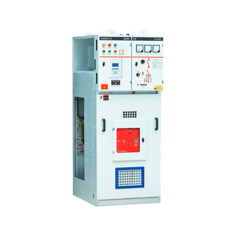
HXGN2-12 AC metal enclosed switchgear Custom
Home / Products / 12kV Medium Voltage Complete Switchgear Equipment / HXGN2-12 AC metal enclosed switchgear

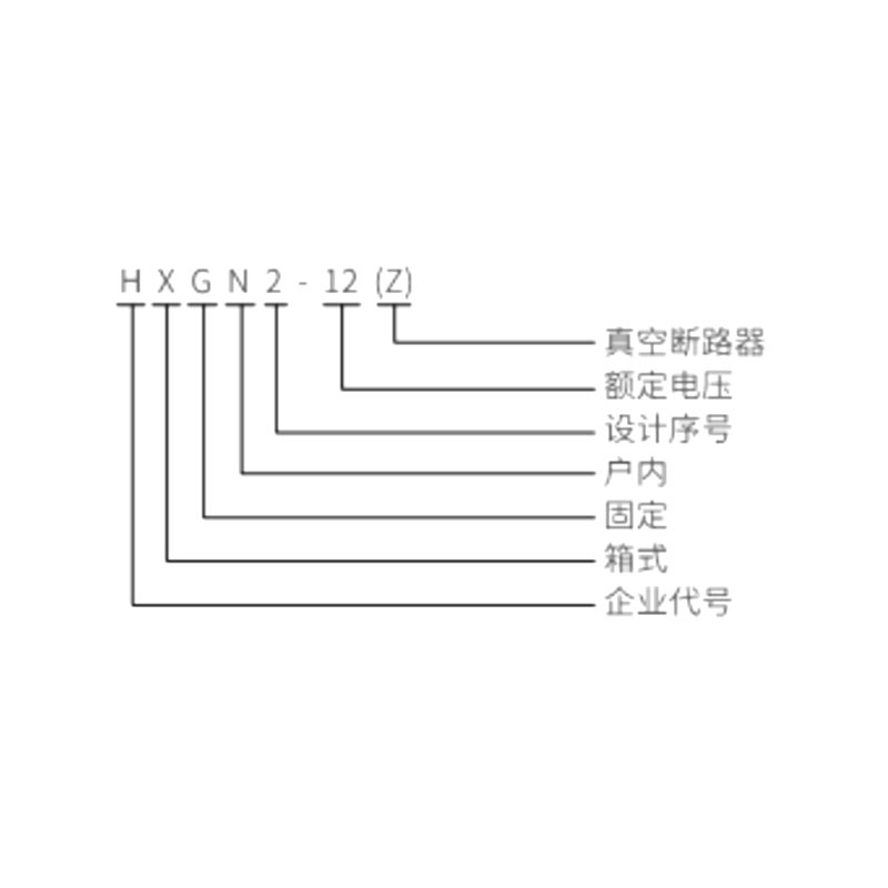 |
Model Designation | |
| H | Enterprise code | |
| X | Box type | |
| G | Fixed | |
| N | Indoor | |
| 2 | Design serial number | |
| 12 | Rated voltage | |
| (Z) | Vacuum circuit breaker | |
| Figure 1 - HXGN2-12(Z) outline dimensions and structure diagram | ||
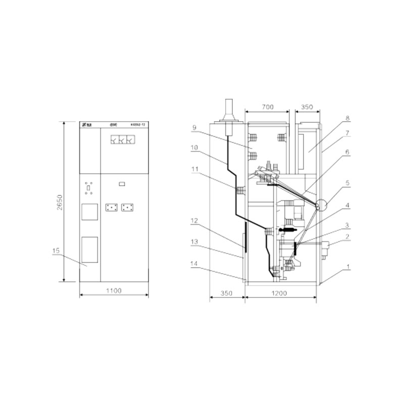 |
1 | Earthing busbar assembly |
| 2 | Vacuum circuit breaker transmission assembly (electric) | |
| 3 | Current transformer assembly | |
| 4 | Lower disconnector transmission assembly | |
| 5 | Operating interlocking mechanism | |
| 6 | Earthing blade upper disconnector transmission assembly | |
| 7 | Front door element assembly | |
| 8 | Relay chamber assembly | |
| 9 | Busbar chamber assembly | |
| 10 | Overhead outgoing line assembly | |
| 11 | Support insulator | |
| 12 | Lighting lamp | |
| 13 | Rear door interlocking assembly | |
| 14 | Main body structure | |
| 15 | Secondary cable installation | |
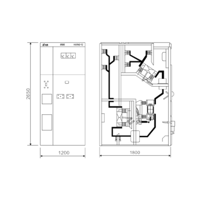
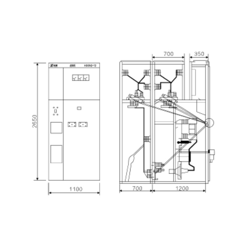
| Figure 2 - HXGN2-12(Z) large current cabinet outline dimensions and structure diagram (equipped with ZN28A series vacuum circuit breaker) | Figure 3 - HXGN2-12(Z) bypass cable cabinet outline dimensions and structure diagram |
 |
 |
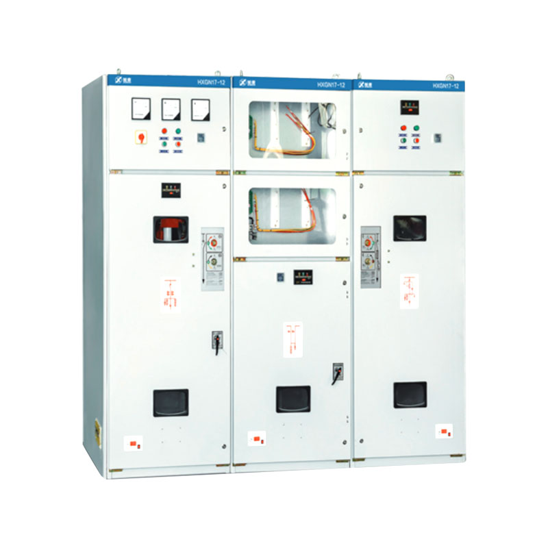
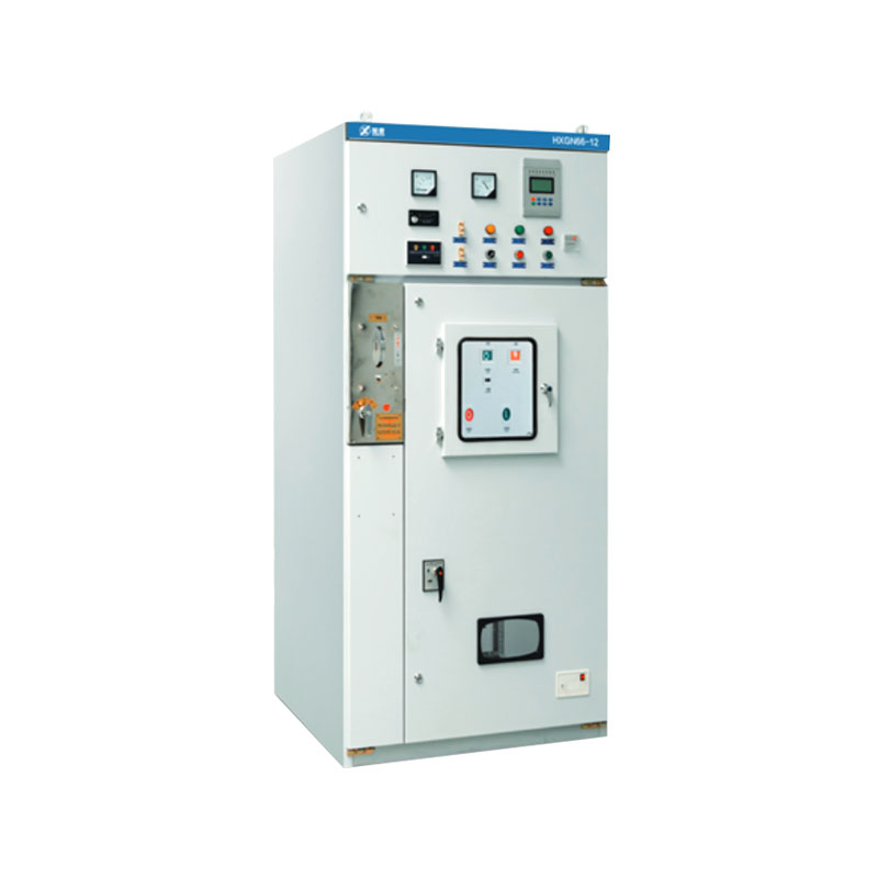
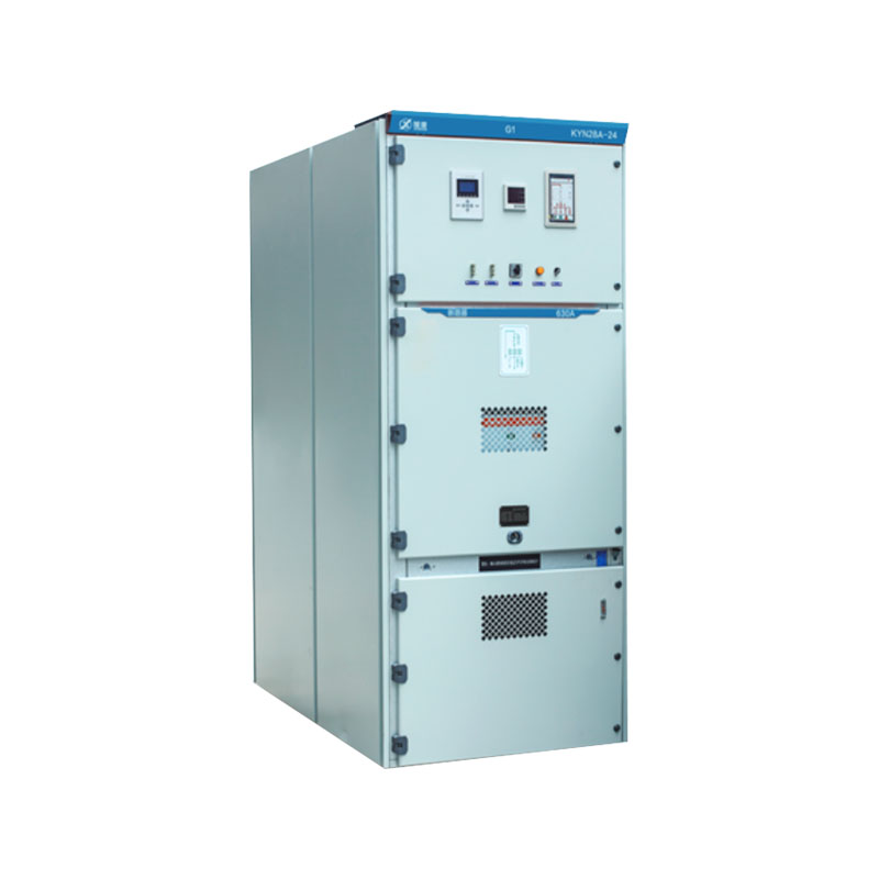

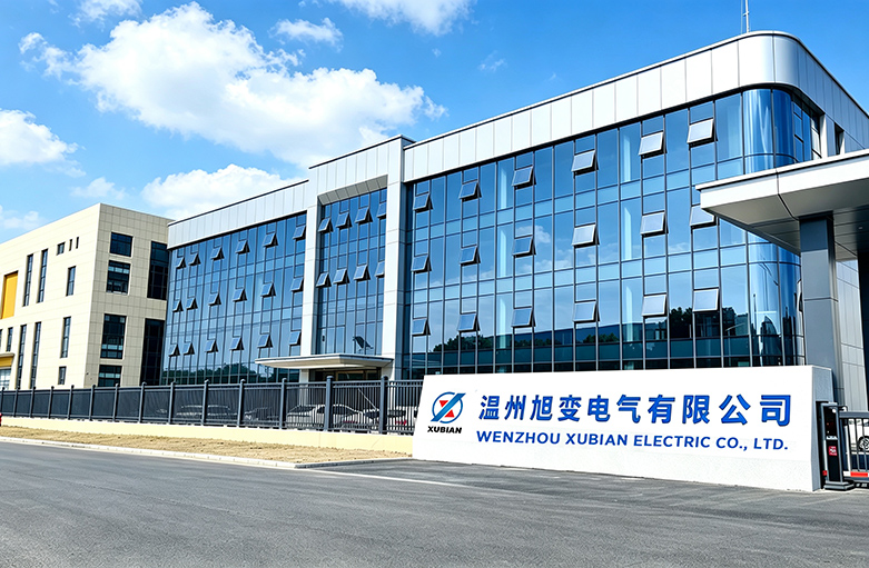
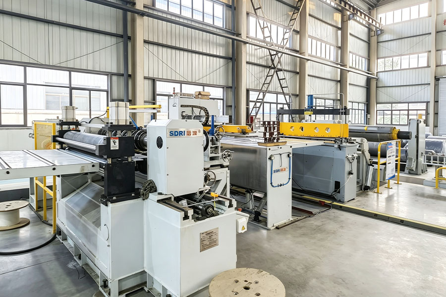
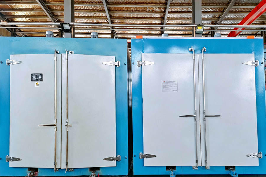
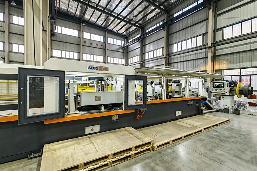
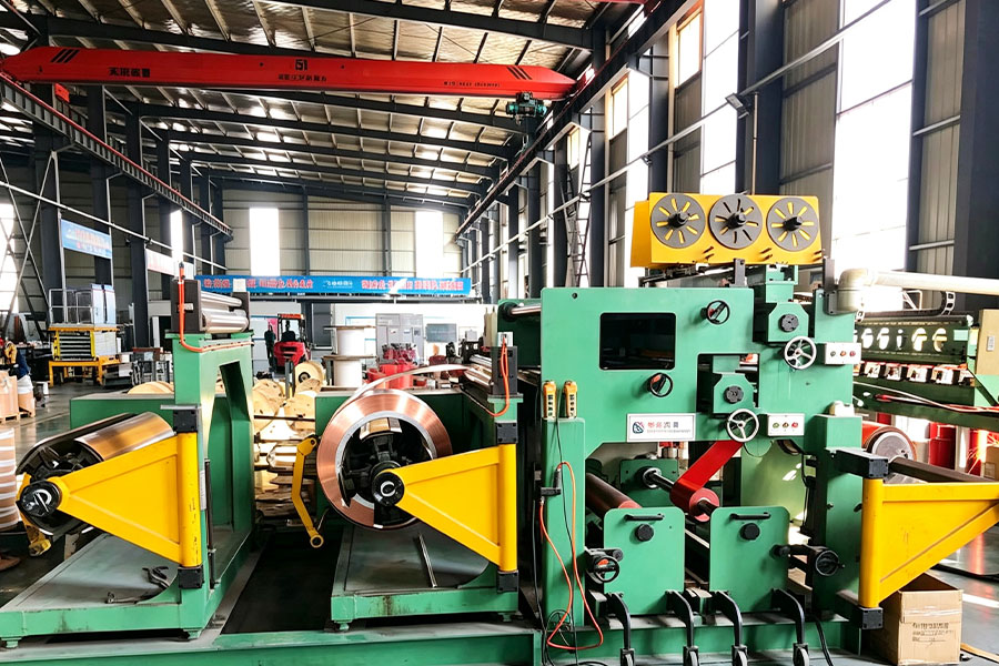
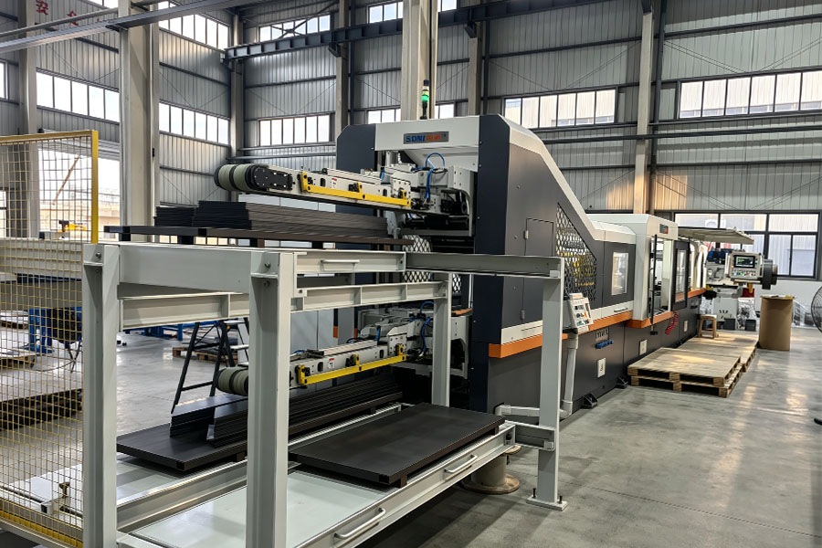
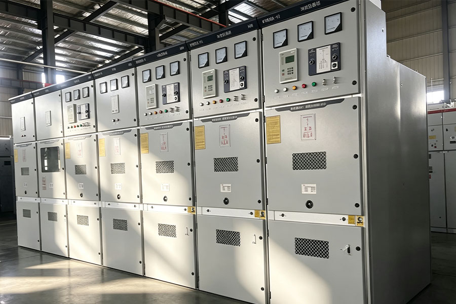
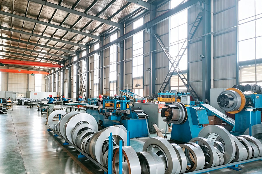
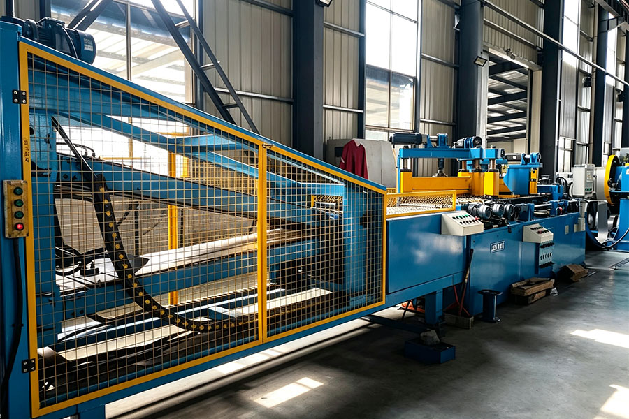
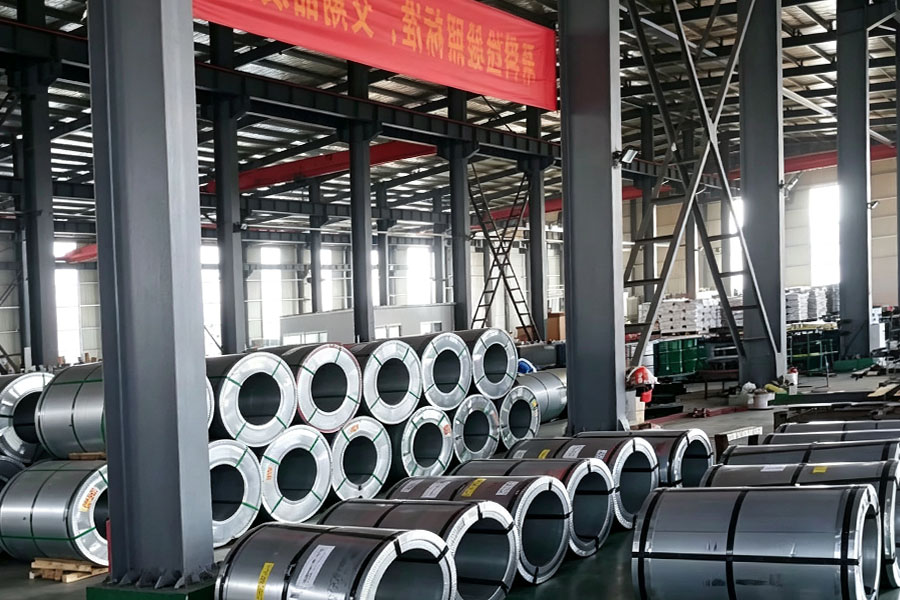
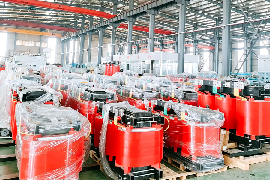
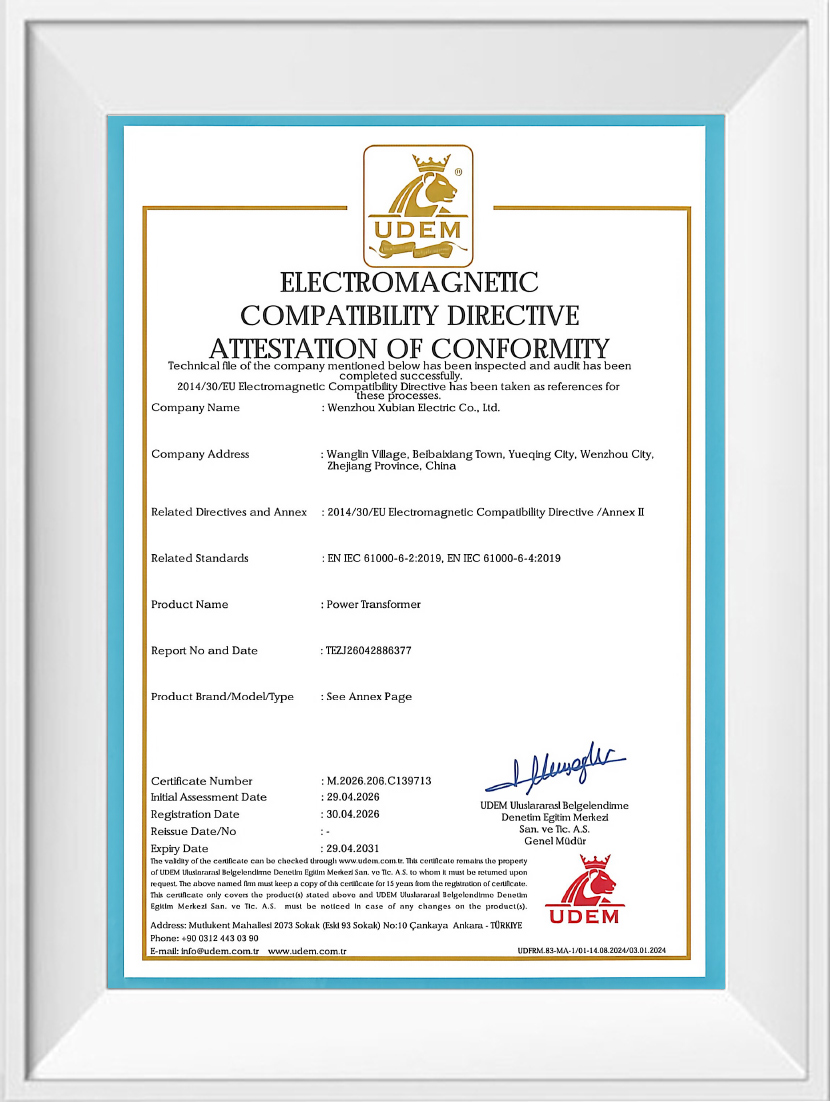
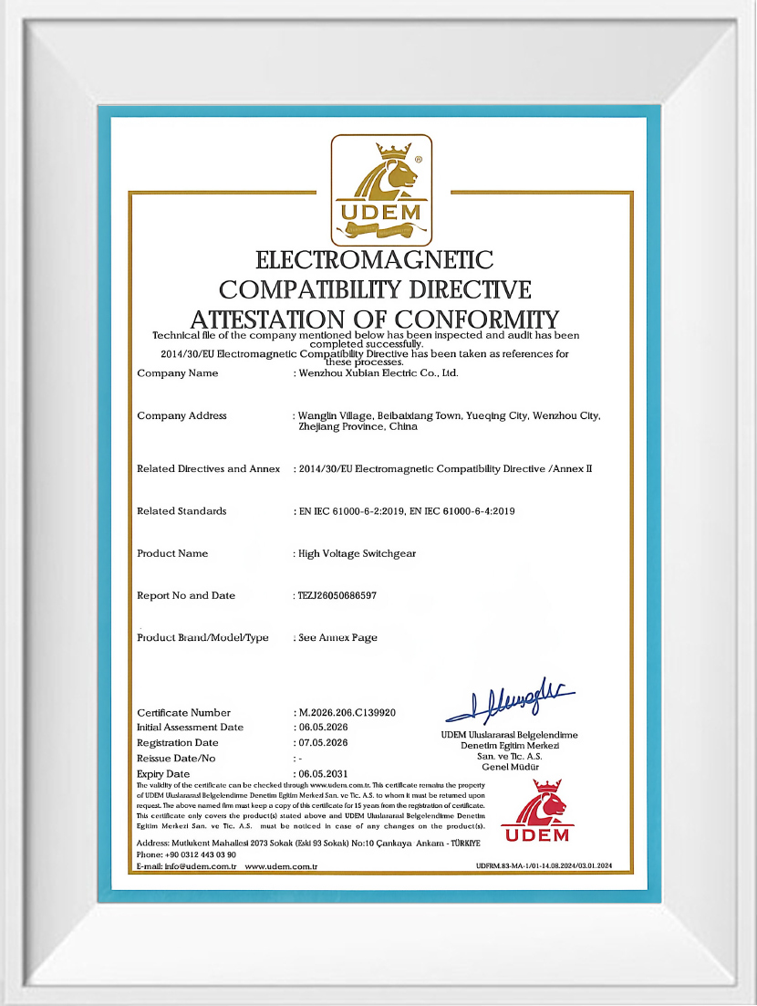
Wenzhou Xubian Electric Co., Ltd. is a technology-driven China HXGN2-12 AC metal enclosed switchgear Supplier and Custom HXGN2-12 AC metal enclosed switchgear Factory, specializing in the production, sales and after-sales maintenance of high- and low-voltage complete switchgear systems.
We have a dynamic and innovative team for R&D, design, management and marketing, backed by solid R&D and production competence.
Following our quality policy: “Survival through Quality, Development through Innovation, Continuous Improvement, Customer Satisfaction”, we enforce strict control over all production stages to ensure 100% qualified finished goods. Our workshop is well‑equipped with full‑range processing facilities, testing apparatus and advanced inspection solutions.

 392635183@qq.com
 +86-0577-62657873
 +86-13858819036
 No.300 Kaixing Road, Xindong Village, Liushi Town, Yueqing City, Wenzhou City, Zhejiang Province, P.R.China